I have long been experimenting with various solar panels initially to try to make some devices more autonomous (eg: self-recharging hexapod robot, long-lasting outdoor camera, etc) and noticed that solar panels have become very cheap and that low quality batteries can also be reasonably cheap. I started to think "what if I used a lot of batteries to power some of my home appliances like servers, water heater, etc?".
Let's do some math. Looking at my electricity invoice, I'm using on average 800W between february and august, and 1400W between august and february. I don't have more details, and both periods include some cold periods where the heating is used. I suppose that taking heating out of the equation I probably need
about 400W on average (light, PCs, water heating).
In order to deliver 400W 24 hours a day with 8 hours of charging, I'd need to charge at 1200W and to store 9.6 kWh of energy. A correct LiPo cell stores 2.6Ah at 3.7V, or 9.6Wh. Thus I'd need 1000 such batteries just to store the required energy. At about $2-3 a battery it's not interesting.
But I thought, why would I need batteries ? Two thirds of my consumption are during the day and one third at night. And these are differently priced so that the day is more expensive (15cts/kWh during day, 10cts at night). So by using 400W of direct solar energy I could expect to be able to cut the day consumption in half, resulting in a 37.5% overall saving on the daily bill.
This approach sounds interesting because it uses 3 times less solar panels and no batteries. But how to power devices on irregular energy sources ?
My idea was that if it were possible to inject the solar energy directly into the mains synchronized with the alternating current, I could in fact offload the energy provider from the energy I harvest from the sun, so that I don't have to care when a cloud passes. But it's possibly very hard to keep in sync with mains...
Then I started to think about some ZVS induction heaters I've made in the past, these ones are resonant self-oscillating circuits. Wouldn't it be possible to do this with mains ? That is, monitor the mains voltage to decide what polarity to send into a transformer ? After all in order to monitor the mains, I just need another independant transformer that's not too much affected by the power I feed into the secondary coil. Thus I ran an experiment with two miniature transformers (12V/1.2VA each) installed behind a 12/230V DC/AC converter (I prefer to use this than real mains during experiments like this). Impressively this worked pretty well out of the box, I could cancel the power consumption of the primary transformer.
That immediately made me think about these old transformers I salvaged from a dead UPS, I remembered they had some additional windings. I took one of them, a 400VA model, measured the voltage across its terminals and found that it matched the markings : 8V symmetric on a 50A circuit (designed to take 12V peaks on its input to produce the 325V peaks), and 14.5V on a low power circuit. This last one would be used to monitor the mains polarity. As long as I don't feed too strong a current, mains will always win and impose its polarity, and this monitoring winding would force the mosfets to reverse the current.
So I came up with the following diagram :

The primary (left part) of the transformer is connected to a power meter and to a 8W/230V lamp. The power meter is connected to the 12/230 converter for now. The assembled circuit looks like this (the MOSFETS are IRFB4110, they are directly mounted on the transformer terminals) :
The wave across the 14V monitor winding looks like this :

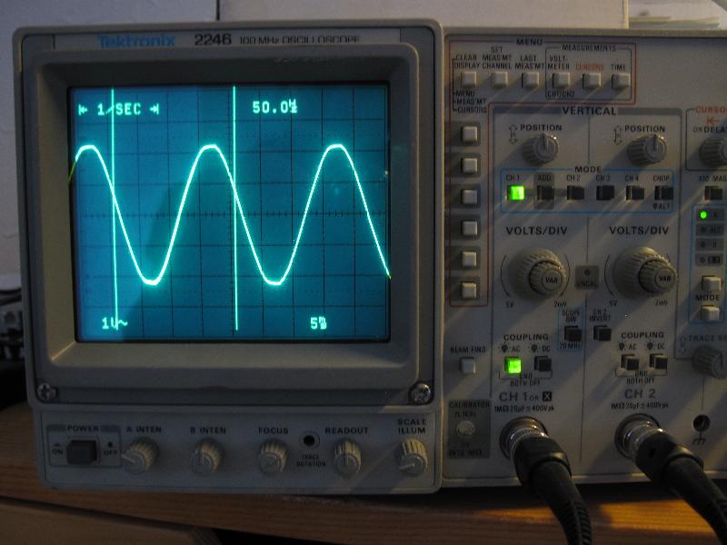
It's obvious that my 12/230 converter doesn't provide a sine wave, it's almost a square one! That's optimal to drive the transistors but it doesn't reflect reality. Since I had no smoke and I could manage to cancel the power usage by adjusting the DC voltage, I restarted the experiment plugged to real mains this time after double-checking every connection. The wave across the 14V winding looks much better :
The power meter showed that the transformer alone draws 4W of power and the lamp draws another 8W, leading to 12W total :
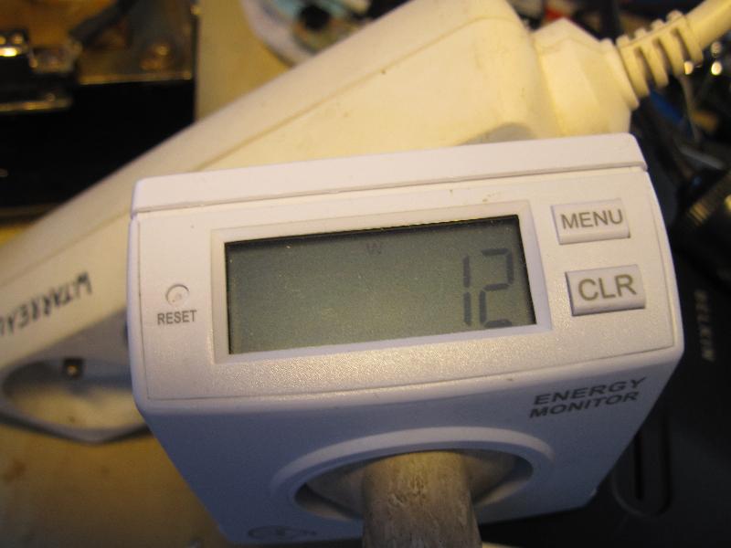
I progressively adjusted the input DC voltage until I saw exactly 0W on the power meter. The DC input showed 8.8V and the amp meter showed 2.26A, that's 19.9W total consumed power to produce 12W of power needed to power the lamp and the transformer losses resulting in 0W on the power meter (I'm not cheating here, except by carefully adjusting the voltage to reach exactly 0, and the white reflect on the LCD comes from the lamp, entirely powered by my circuit) :


Note that some of these 19.9W are in fact injected into the mains, this explains why almost nothing heats here and why a higher current was needed to cancel consumption when connected to mains than to the DC/AC converter. Pushing the DC voltage higher results in the power meter showing a positive power again, indicating that I'm sending even more power into the house. At this point I stopped the experiment.
So yes, it is technically possible to re-inject some power into mains with a simple enough circuit. At this point one difficulty is to find the proper input DC voltage to cancel the mains without sending too much, because I don't want to dissipate too much power nor to send power back into the grid (with even the risk that it would make the disc spin again and charge me for the power I offer). Probably that producing only the minimum of any day's power usage would be a very simple way to solve this. Otherwise maybe a current meter on the mains connection to the grid could make it possible to have some feedback and regulate the injected power.
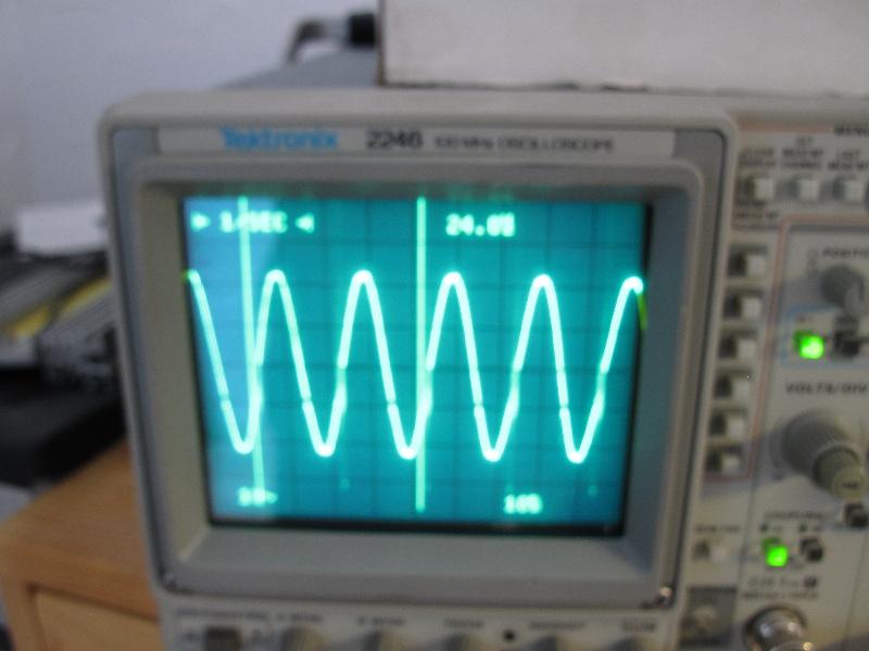
It's worth noting that during this experiment the delivered current was not very clean. On the image below it's visible that there were short peaks at each zero-crossing, caused by the short period during which none of the MOSFET is conducting, I even had to change the scope's time base because it couldn't stabilize on it :
But these artefacts should be very easy to cancel using a small capacitor across the transformer's terminals connected to the MOSFETs and it will also increase the efficiency and limit the MOSFET heating. Note that during this experiment, the MOSFETs were barely warm. Another improvement could consist in using a voltage comparator to always saturate the MOSFETs during the switch but given that the voltage is low at this moment it's not even certain that this is needed. I should also possibly use a choke in series with the central point of the transformer to absorb current impulses during the polarity inversion. But all this is very cheap and just a matter of experimenting a little bit.
Good solar panels having about 20% efficiency are found around $1/W nowadays, so for $400 it's possible to build a 400W array. Feeding 400W of power into the mains 8 hours a day every day at peak energy cost would save 175 EUR/yr, so the panels and circuits would be amoritzed in 2.5 years approximately.
Note that I thought about charging batteries at night and re-injecting the power during the day, but the cost difference and the inevitable losses would not make this worth, and it would take decades to amortize the batteries cost.
Has anyone successfully tried such a design ? Suggestions welcome.
I'm just looking at this. I'm utterly astonished that it is not already commonly done. Unless it is. I'll keep looking. enjoyed your article...
ReplyDelete